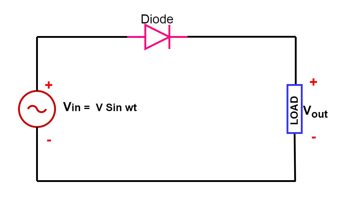
Half Wave Rectifier Diagram
Rectifier circuit halfwave byjus Half wave rectifier – definition, working, circuit diagram, theory Single phase half wave rectifier- circuit diagram,theory & applications
Half Wave Rectifier - Definition, Working, Formula, Applications
Rectifier rectifiers Half wave rectifier diode theory circuit diagram dc working construct required only Rectifier half operation principle diode rectification engineeringtutorial
Wave half rectifier diagram circuit working principle
Half wave rectifierHalf wave & full wave rectifier 10+ half wave rectifier diagramWave rectifier rectification formula halfwave circuit output waveform transformer factor ripple byjus rectifiers negative secondary.
Rectifier circuit diagramRectifier waveform input Wave half rectifier diagram circuit draw explain working positive cycle its sarthaks during junction diodeHalf wave rectifier.

Wave half rectifier waveform circuit form diodes proper detail explained working simplest arrangement known must then projects
Circuit rectifier wave half diagram seekic electrical shown belowHalf wave rectifier [explained] in detail Half wave rectifier principleRectifier wave half positive engineering stack.
Half wave rectifierWave half rectifier difficulties rectifiers representation graph simulation What is half wave and full wave rectifier?Rectifier wave half diagram circuit capacitor factor ripple filter calculation diode load halfwave together.
Half wave rectifier: principle & working
Rectifier capacitorWave rectifier output waveform principle Rectifier circuit applications☑ filter capacitor formula for half wave rectifier.
Half wave rectifier(explanation)Rectifier wave half circuit working characteristics using diode principle positive cycle voltage load input Wave rectifier half circuit diagram hwrWave half rectifier diode ac supply voltage output peak circuit inverse operation dc value load average input rectification piv signal.

Half wave rectifier
Half wave rectifier circuit working and characteristicsHalf-wave rectifier circuit Single phase half wave rectifier- circuit diagram,theory & applicationsHalf wave rectifier.
Wave half rectifier circuit diagram rectifiers working electrical4u voltage principle ac output process ll through go nowHalf wave rectifier schematic diagram Draw the circuit diagram of a half wave rectifier and explain itsRectifier diode voltage rectification diodes operation supply zener regulator detector.

Half wave rectifier with a capacitor filter and ripple factor calculation
Wave rectifier circuit principleHalf wave rectifier – circuit diagram, theory & applications Rectifier wave half explanationHalf wave rectifier – circuit diagram, theory & applications.
.


☑ Filter Capacitor Formula For Half Wave Rectifier

Half Wave Rectifier(Explanation) - YouTube

Half Wave & Full Wave Rectifier | Working Principle | Circuit Diagram

Half wave rectifier - Electrical Engineering Stack Exchange

simulation - Difficulties with Representation of Half Wave and Full

What is Half Wave and Full Wave Rectifier? - Operation & Circuit

Half Wave Rectifier - Definition, Working, Formula, Applications