H Bridge Ups Circuit Diagram
Bridge inverter ic fet driver current suburbia sustainable typical Inverter methodology input simulation uninterrupted rfi Inverter circuits
Single-phase UPS based on half-bridge converter-inverter and a
H bridge design Circuit inverter converters inverters igbt bipolar transistors (pdf) design and simulation of online uninterrupted power supply
H bridge
Cascaded four considered inverter unipolarCircuitlab stack Bridge converter schematic boost circuit supply power circuitlab created using stackCircuit relay polarity arrangement altered directions mechatrofice.
Circuit schematic of three-level h-bridge inverter and simplified blockA functional circuit (h-bridge topology) of the power supply Ic 555 inverter circuit diagram – diy electronics circuit projectsHow to make h bridge using ir2110.

Inverter converter chopper buck
H-bridge power supply shortingBridge ir2110 driver circuit using diagram gate mosfet inverter make microcontrollerslab projects источник статьи voltage Inverter diagram inversor sine wave ponte onda senoidal circuitoH-bridge power supply.
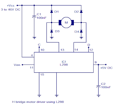
Dc motor direction control using relay circuitInverter bridge au kemet digikey Motor circuit bridge dc l298 diagram control ic using driver controller bidirectional schematic electronics projects based power electrical student pwmBoost converter as power supply for h-bridge.
Simple h-bridge motor driver circuit circuits diy simple electronic
H-bridge inverterH bridge motor controller circuit diagram Topology functionalSpwm regulates voltage in dc-ac inverter designs.
Bridge circuit motor driver circuits simple mosfet dc using transistor working diyBridge inverter circuit ic diagram electronics configuration Inverter spwm regulates edn renewable blocksSustainable suburbia: open inverter part 4.

Shorting supply bridge power
Dc-to-ac converters (inverters): design, working & applicationsSchematic diagram of the considered four-level cascaded h-bridge Single-phase ups based on half-bridge converter-inverter and aSchematic of the inverter circuit of h-bridge.
Inverter simplifiedCircuit bridge brigde simplifying transistors Circuit diagram of h bridge inverterTypical single-phase full-bridge (h-bridge) inverter..


H-Bridge Inverter - KEMET | DigiKey

Schematic of the inverter circuit of H-bridge | Download Scientific Diagram

H-Bridge power supply shorting

Circuit Diagram Of H Bridge Inverter | Wiring Diagrams Nea

h bridge - Simplifying H-brigde circuit - Electrical Engineering Stack

Single-phase UPS based on half-bridge converter-inverter and a

SPWM regulates voltage in DC-AC inverter designs - EDN Asia

A functional circuit (H-bridge topology) of the power supply